The Bluetooth standard has been organized into well defined set of stacks. Each stack has a specific functionality. Some stack are standard implementations that all devices should have while others are required based on the functionality of the device. The figure below shows the overall Bluetooth stack architecture.
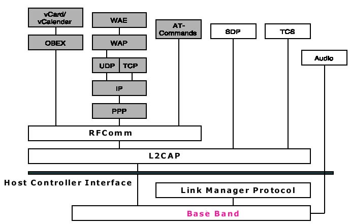
The Bluetooth standard is divided into two broad categories. The Core refers to the technology, protocol and format of the data exchange of the Bluetooth device. The Profiles cater to a particular functionality of the Bluetooth device. The Profiles require the presence of the Core standards for its functionality.
The radio link provides specifications for the frequency and characteristics of the Transmitter and Receiver. It lays down the guidelines for modulation, emissions, interference and tolerance levels. This information is mainly catering to hardware manufacturers who provide Digital Signal Processing (DSP) chips for Bluetooth devices.
To transmit signals the bluetooth technology uses GFSK (Gaussian Frequency Shift Keying) method. This means that a bit of 1 is represented by a positive frequency deviation while a bit 0 would be represented otherwise.
For this project we will use a BT500 Acer Adapter which belong to the Power Class 2 of the power consumption class. This means it only has a range of 10 meters and a maximum output of 2.5mW. Any bluetooth device works within the 2.4Ghz frequency (2.4 to 2.4835GHz).
Operating in the 2.4 GHz industrial band , with individual frequencies of 1 MHz each, the bluetooth band uses 79 or 23 RF channels . Each channel is divided in 625 m/s intervals , equivalent to 1600 jumps per second. The frequency is modified to each new time interval. Another reference to the channel, consists of a pseudo-random sequence of these 79 (or 23) RF channels.
In Bluetooth, the communication is made using frequency hopping (spread spectrum), being used all the interval from 2400 MHz to the 2483,5 MHz, making 79 jumps of 1 MHz, starting in 2,402 GHz up to 2,480 GHz. There are some differences in some countries , however in all of them, there are superior and inferior limits for the band intervals .
A channel is formed by the pseudo- random sequence of jumps, using the FHSS method to prevent interferences. An interference occurs when one particular RF channel coincide with the frequency of the Bluetooth channel. T his occurs only 1.3% of the time in a system with 79 canals. The range of the bluetooth connection can be increased, by increasing the power of the transmission . Which is not the case in this project.
Synchronous Connection-Oriented Link (SCO)
This mode of connection is a point-to-point connection between two devices. The connection is mainly used for transmission of time bound data like voice. Thus the data is never retransmitted. The Master reserves a specific time slot for the transmission. This time slot is dedicated for the transmission of the data packets to the Slave device. Thus, the connection is equivalent to a Circuit switched connection link. The Slave and the Master communicate through a fixed slot assigned to them. A Master can support up to 3 SCO links to the same Slave or to different Slaves. A Slave can accept up to 3 SCO links from the same Master, or up to 2 SCO links from different Masters. A Slave can transmit data if it is not addressed by the Master or if it fails to decode the previous message sent by the Master.
This type of connection will not be used in this project.
Asynchronous Connectionless Link (ACL)
This mode of connection can be a point to multipoint connection between all active Bluetooth devices in a Piconet. A Master can have only one ACL link with another Slave. The connection provides, retransmission and error checking capabilities. A Slave cannot send a message to the Master if the previous message is not addressed to it, or if the Slave fails to decode the message .
Because of the asynchronous nature of this type of connection, the group chose to implement this type of connection.
Generally, the baseband data is sent over the air in the form of packets with the least significant bit sent first. The packets are broken down into 3 fields- The Access Code, The Header and The Payload as shown in the figure below

The Access code has a size of 72 bits or 68 bits (depending on the type of data packet sent), and the Header has a fixed size of 54 bits. The Payload consists of the data being carried and may range from 0 to 2745 bits. All data sent between Bluetooth devices should have an Access Code. The packet may or may not contain the Header and Payload information, but should have an Access code.
Access Code
There are generally 3 access codes available
- Device Access Code (DAC)
- Channel Access Code (CAC)
- Inquiry Access Code (IAC)
- General Inquiry Access Code (GIAC)
- Dedicated Inquiry Access Code (DIAC)
| AccessCode | Access Name | Bit Size | Description |
| DAC | Device Access Code | 68/72 | Code to access a device during Paging operation. |
| CAC | Channel Access Code | 72 | Code to create a connection between two devices. |
| IAC | Inquiry Access Code | 68/72 | Codes, used during the Inquiry phase. |
| GIAC | General IAC | 68/72 | Code to access all Bluetooth devices. |
| DIAC | Dedicated IAC | 68/72 | Code to access a specific Bluetooth device. |
The Access Code is itself broken down into sub fields-Preamble, Sync Word and Trailer, as shown in the figure below
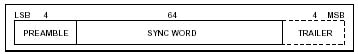
The Preamble is a 4 bit sequence of alternate 0 and 1 depending on the first bit of the subsequent Sync Word. There can be two values of 0101 or 1010 depending on the first bit of the Sync Word is 0 or 1. The Sync Word is a 64 bit code that is derived from the 24 bit LAP. The Sync Word is derived from the Master BD_ADDR's LAP if the packet is for Channel Access. IF the packet is for Device Access, the LAP of the Slave is used and if the packet is for Inquiry Access, a standard LAP value is used. The Trailer is a sequence of 4 bits of alternating 0 and 1 depending on the last bit of the Sync Word. The Trailer is used if the Sync Word is followed by the Header Field, but may also be used in other cases.
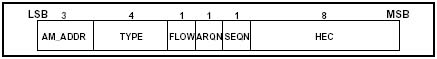
Header
The Header information is shown in the figure below
| Header Name | Bit Size (Bit location) | Description |
| AM_ADDR | 3 (0-2) | Temporary address assigned to each active Sla v e in a Piconet. 000 is for broadcasting. |
| TYPE | 4 (3-6) | The type of data packet sent. There are 16 types. It also specifies the length of the packet so that Slaves can listen in on the same frequency and other slaves can wait for the duration of the packet transmission before hopping to the next slot. The type is dependant on the type of connection, i.e., ACL or SCO. |
| FLOW | 1 (7) | To inform the continuity of data flow. If the buffer in the recipient is full, a STOP (0) is sent to temporarily hold further data transmission. A GO (1) is sent for indicating that the recipient is ready to receive more data packets. |
| ARQN | 1 (8) | To inform the sender of the acknowledgement of the reception of a data packet. ACK (1) is sent if the data is successfully received. A NAK (0) is sent if data was not received or contains errors. NAK is the default. |
| SEQN | 1 (9) | Determines the sequence of received packet. Each consecutive packet would have opposite bit values. Two subsequent packets with the same bit value indicates a retransmission. |
| HEC | 8 (10-17) | Value to check for the integrity of the header information. |
Link Manager
The specification deals with the set up and control of the logical channels. The signals received from the lower layers are processed here without propagating them to the higher layers. The link manager controls the state of the current Bluetooth device as well as manages the connection with other Bluetooth devices in the Piconet.
This specification describes the Bluetooth
logical link control and adaptation protocol (L2CAP). This protocol
supports higher level protocol multiplexing, packet segmentation and
reassembly, and the conveying of quality
of service information. The specification describes the protocol state
machine, packet format and composition, and a test interface required for
the Bluetooth test and certification program. The L2CAP layer is concerned
with packet data transmission only and not with voice data. Thus a
Bluetooth device like a headset may or may not contain this layer.
Service Discovery Protocol (SDP)
This layer lays down the specification for the process and procedure for a Bluetooth device to discover the functionalities available in other Bluetooth devices.
RFCOMM (Serial Port Emulation Protocol)
This layer provides an emulation of the serial port communication commonly found in Personal Computers. It follows the standard (subset) of the ETSI's TS 07.10 specification. for serial port emulation.
Host Controller Interface (HCI)
The Host Controller Interface is not a protocol layer. It provides a standard transport and communication interface which all Bluetooth devices are to follow. This allows wide inter-operability between different manufacturers. Thus applications that are designed and developed on one Bluetooth device can be made to run on other Bluetooth devices from different manufacturers.
This layer provides a method of accessing the hardware interface through a set of standard calls. This method eliminates the need for higher layers to know the detailed functionality of the Bluetooth device, thus providing a level of indirection between the lower and the upper layer.
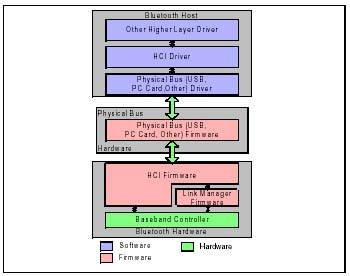
The above diagram shows the location of the HCI interface. The HCI interface e links the Bluetooth device to the host system. The host system can be anything from a PC to a embedded device. To access the HCI interface, the host system communicates the commands through a physical bus. Thus, the intermediate physical bus needs a firmware that allows the transportation of the HCI commands to the HCI layer on the Bluetooth device without knowing the details of the commands. Currently only USB, PC Card and UART are supported as the bus interface layer. The HCI layer also helps provide asynchronous notification of events to the host.
Normally, while developing Bluetooth devices, the HCI interface is the most commonly called and utilized interface. Most of the available products and development boards come with the HCI interface layers.

The above figure shows the block diagram of a Bluetooth hardware architecture taken from the specifications. The HCI interface reveals most of the control commands to control the device. However, the CPU core that takes care of the Bluetooth device can also be programmed.
HCI Flow Control
The HCI flow control's main purpose is to control the amount of data being sent between the host and the Bluetooth device. Since the Bluetooth device may have a limited buffer storage area for storing the data packets to be sent, the host needs to take care of this limitation and not flood the device with excess information. Thus, the Flow control provides a method of accessing the buffer size and the amount of buffer area left at any point of time through an event based trigger.
The other function of the flow control is to make sure that the data sent from the host to the device is sent over the air without any modification. thus the first bit received from the host is the first bit sent over the air by the Bluetooth device. This is also similar to the data received from the other Bluetooth device and that is being sent to the host system.
HCI Commands
The HCI commands are broken into three broad categories based on their functionality. They are as follows
|
HCI command category |
Description |
|
HCI Link Command |
Provide link layer level control |
|
HCI Policy Command |
Provide method to control the behavior of a Piconet |
|
HCI Host Controller & Baseband, |
Provide direct access to various registers in the controller |
- General
Each command is provided with a 2 byte (16 bit) Opcode to identify the command. The 2 bytes are divided into two fields
|
Field |
Bit length |
Reserved values |
|
Opcode Group Field (OGF) |
6 bits (10-15) |
0x3F reserved for vendor specific debug commands 0x3E reserved for bluetooth logo testing |
|
Opcode Command Field (OCF) |
10 bits (0-9) |
0 - 0x03FF |
The HCI interface handles different kinds of packet structure depending on whether the data is HCI Command, HCI event or HCI data packets.
- HCI Command Packet Structure

The first 16 bits form the Opcode to describe the kind of command. The Parameter Total Length represents the length of all the parameters associated with this command. It should not be mistaken with the number of commands. The number of parameters and their sizes in integers, is defined for a specific command.
Usually, when an HCI command is sent from the host to the controller, an event is generated whenever the command is processed. However, some commands do not have an event associated with them. The controller sends a command status packet back to the host upon processing of the command .when the processing is complete, an event associated with the command is sent back to the host.
- HCI Event Packet Structure

Each event has a uniquely defined event code of length of 8 bits. The Parameter Total Length represents the total length of all events in the packet. Again, it is not the total number of events in the packet. The number of event parameters depend on the event code.
- HCI Data Packet Structure
Represents the data exchanged between the host and the controller. The data packet format is different for SCO and ACL connection types.

The above figure represents the data structure for the ACL connection type. The figure below shows that of the SCO connection type.

Both of the data packets have a Connection Handle field to represent the connection from which the data originates or destination to which the data is destined. They also have a Data Total Length field that represents the total length of the data in the packet.
The difference lies in the Packet Boundary Flag and the Broadcast Flag of the ACL connection. Since an SCO connection is a point to point connection, there is no requirement for broadcast information. However, for ACL link, where the configuration can be a point to multipoint connection, there is a need for broadcasting of information to all associated devices in the Piconet.
The Packet Boundary Flag indicates to the receiver, whether the packet received is a totally new packet or is part of a series of packets.
>Simple HCI Commands , Event and Error Tables <
HCI Connection Handle
A connection handle is a 12 bit representation of a channel connection between two Bluetooth devices. The connection handle is used within a host-controller device. There can be multiple connection handles between two Bluetooth devices. However, they all refer to the same ACL channel. A connection handle exists for the duration of the connection no matter what state the Bluetooth devices are in.
While sending and receiving information between Bluetooth devices, the connection handle is used to refer to the application that has sent the message. Since two communicating devices can have multiple applications running between them ,the connection handle provides a way of distinguishing the application that sent the data packet.